

Compressed Air Treatment Guide
Impurities in the compressed air of a pneumatic system can result in the formation of condensate in the piping, greatly affecting the performance of a pneumatic system. To prevent that, pneumatic equipment requires clean, dry, and oil-free supply of air. We need to treat and filter the air passing through a pneumatic system to ensure that. In this article, we will examine the processes and components involved in that air treatment.
Overview
A compressed air treatment can be divided into three stages as illustrated below. In the first stage, we have a compressor inlet filter and aftercooler removing large particulate matter and water content respectively from the air. The air, still wet, is collected in the wet air receiver. From the wet air receiver, the air is passed through a refrigeration dryer and general-purpose filter for primary air treatment. The treated air is collected in the dry air receiver.
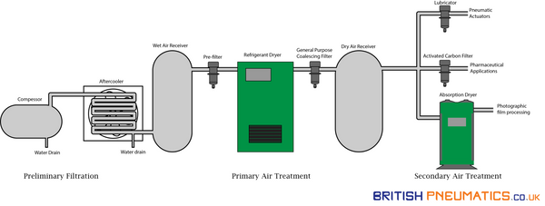
The air in dry air receiver, depending upon the primary treatment, is suitable for general industry use. For specific applications, like medical applications or automotive paint jobs, the air is treated further by passing through finer filters, which is the secondary treatment of air.
2. Preliminary Filtration
As the name gives away, preliminary filtration is performed before core air treatment. It is performed to prevent large particulate matter from damaging the compressor and fine filters and remove easily removable moisture from the air.
2.1 Intake filters
While air used in compressors is, usually, sourced from outside the plant to avoid contaminant-intense plant air, the outside air, still, has a dust concentration of 15-45 mg/m3. To prevent these dust particles from entering the compressor, coarse filters are used. These filters prevent more than 99 % of particles from entering the compressor. The usual filter types and their respective characteristics can be seen in the table below.
|
Filter Type |
Characteristics |
|
Paper Filters |
|
|
Fabric Filters |
|
|
Oilbath Filters |
|
|
Labyrinth type oil wetted filters |
|
|
Inertial filters |
|
Table 1. Types of Pneumatic Filters
2.2 Drains and Aftercooler
Intake filters are only effective at removing particles larger than 5 microns from entering the compressor. Smaller particles, water vapours, gases, and microbes are still allowed to pass through. Of these contaminants, the amount of water vapours is limited by the allowable amount at saturation. For example, 1 m3 of air can contain 12.7 g of water at atmospheric conditions at 15° C. This saturation limit increases with an increase in temperature and decreases with an increase in pressure.
While a compressor increases both pressure and temperature, the net effect is a reduction in the saturation limit. For example, when compressed to 4 bar and 35°C, the same air will retain only 7.87 g of water. Thus, 4.83 g (12.7-7.87) of water per m3 of air will have to be drained from the compressor.
As a reduction in the temperature can further reduce the saturation limit, an aftercooler is always used after the compressor. For example, if the air in the previous case is cooled to 25°C, an additional amount of 3.10 g (7.87-4.77) of water per m3 of air can be removed.
3. Primary Air Treatment
After the aftercooler, the air is stored in the wet air receiver (wet because air still contains moisture). Many pneumatic devices involve sudden expansion of air, therefore, the remaining moisture is still problematic. It can result in the production of ice in the passage and block exhaust, rendering a tool useless. Similarly, the moisture in the air causes corrosion and reduces the effectiveness of lubrication. Thus, these contaminants are to be removed. The usual devices for which are below.
3.1 Pre-filters
Pre-filters are usually installed right after the air receiver in cases where expected contamination is very high. It contains filter elements of sintered stainless steel, sintered bronze, or polypropylene with pore sizes of 5-25 microns. The air flows from inside to out, leaving the larger contaminants inside the filter and protecting the finer filter devices downstream.
3.2 Refrigerant Dryer
Dew point temperature of the air is the temperature at which the air is saturated with water vapours. Any decrease in temperature from that point results in the production of condensate. To prevent that from happening, the dew point temperature of the compressed air is to be maintained lower than the ambient air temperature.
Refrigerant dryers are commonly used for reducing the dew point in pneumatic systems. They facilitate heat exchange between a refrigerant and the compressed air, thus cooling the air. The air is cooled to 2-5 °C, resulting in the removal of excess water and lowering of dew point temperature. The cool air is warmed through the heat exchange with the inlet air to increase the efficiency of the system and to bring the air back to the system’s operating temperature.
3.3 General Purpose Coalescing Filter
Using pre-filter, we get rid of most of the particles above 3-5 microns. The smaller dust particles, oil droplets, and debris in the pipeline will, however, still be present in the air which can damage valves and cylinder downstream. To prevent that from happening, we use a general-purpose coalescing filter in most applications.
The construction and working of a general-purpose coalescing filter are illustrated below. At the air inlet, there are angled louvres, which cause the air to start spinning about the centre. Due to the centripetal force, the heavier particles are thrown against the wall. From where they fall toward the filter bowl, to be removed. The remaining air passes through the filter elements toward the air outlet. The coalescing type filter elements are successful in removing most of the aerosol particles (> 1 micron) and solid particles (> 0.4 microns).
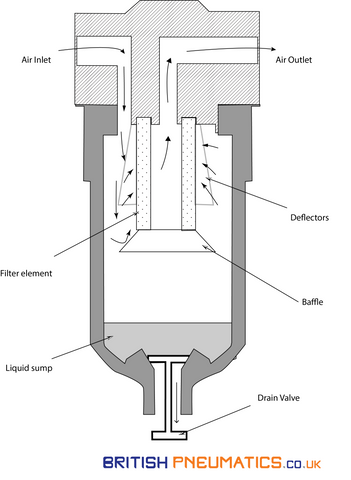
Figure 2. Pneumatic Coalescing Filter Cross-Section
4. Secondary Air Treatment
After primary air treatment, the air is forwarded to the dry air receiver. The air treatment so far should be sufficient for most of the typical applications. Nonetheless, for sensitive applications like those in pharmaceutical industries and optical industries air require even stricter treatment. Therefore, air the collected in dry air receiver is passed through additional devices of secondary air treatment prior to its point of application. The usual devices involved in secondary air treatment are discussed below.
4.1 Absorption Dryer
In applications like air spraying, air bearings, and photographic film processing, any moisture content is extremely damaging. The dew point temperature requirements are usually below freezing point up to -70 °C, rendering refrigeration dryer inadequate. As a result, we require chemical drying to remove the moisture content and reduce the dew point temperature.
The usual absorption dryers are of the regenerative type and occur in twin tank construction, each of which contains desiccant material like silicon dioxide in the form of a gel to absorb moisture. During operation, one tank is absorbing the moisture, while the other is regenerating by hot-air flow as shown in the figure below.
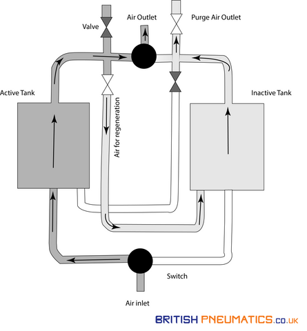
Figure 3. Air Dryer
4.2 Activated Carbon Filter
In critical applications like those in hospitals and the pharmaceutical industry, we have stricter requirements for odour and oil vapours. For such cases, a filter with activated carbon in finely granulated form is used. It removes oil content up to 0.01 microns, which is considered oil-free.
4.3 Lubricator
The working of a lubricator is similar to that of a carburettor. The air passing through a lubricator is passed through a venturi ring, causing an increase in velocity and a decrease in pressure. As the pressure drops, the oil present in the linked chamber starts to move toward the venturi ring in the form of droplets due to pressure difference. These oil droplets mix with the incoming air to form a fine mist, which is sufficient to lubricate the downstream devices.
4.4 Which device should you include?
As hinted in the first figure at the top, the required air treatment depends upon the end application. At a given plant, one compressor may be supplying air for both spray painting and general-purpose applications. It would be expensive to use the air standards of spray painting on general-purpose applications. Therefore, it is recommended to design the air treatment system for general purpose applications and install secondary treatment for specific applications. In that case, the table below gives a general overview of when to use a specific device in your system.
|
Contaminant |
Criterion |
Requirements |
Devices |
Applications |
|
Water |
Dew Point |
Above 10 |
No additional device |
General Purpose |
|
3 to 10°C |
Refrigerant Dryer |
Construction and mining |
||
|
-7 to 3°C |
Single Tower Desiccant Dryer |
Brick and glass machines; Machine cleaning air |
||
|
-70 to -7°C |
Regenerative Desiccant Type Dryers |
Spray painting, Food handling, and Photographic film processing |
||
|
Oil |
mg/m3 |
25 |
No additional device |
Construction, mining, and welding |
|
5 |
Pre Filter |
Power circuits and machine cleaning air |
||
|
1 |
Coalescing filter |
Packaging and textile machines |
||
|
0.1 |
High-efficiency coalescing filter |
Conveying of power products |
||
|
0.01 |
Activated Carbon Filter |
Photographic film processing and food handling |
||
|
Dirt |
Particle Size (μm) |
Above 40 |
No additional devive |
Sandblasting |
|
40 |
No additional device |
Mining and machine tools |
||
|
5 |
Pre Filter |
Spray painting and pneumatic cylinders |
||
|
1 |
General Purpose Coalsesching filter |
Air bearings and food handling |
||
|
0.1 |
High efficiency coalescing filter |
Photographic film processing |