

How to Choose a Solenoid Valve for Pneumatics
1. Introduction
Pneumatic solenoid valves are electro-mechanical components of a pneumatic system that help control the flow conditions of compressed air. In turn, these conditions determine a multitude of events, such as whether a linear cylinder extends or retracts. The underlying principle behind solenoid valves lies in the solenoid coil, such that if an electrical current pass through this coil, a magnetic field is generated. The magnetic field, subsequently, moves the spool within a valve body. But owing to the shape of this internal spool, the flow path of compressed air is manipulated. That is – compressed air will flow to a specific outlet port depending on the position of a spool.
Solenoid valves vary in specification along a number of different dimensions. It is imperative to select the right solenoid valve for the application. The dimensions include the number of ports, the number of ways, the voltage of the solenoid coil, and the material composition of the valve.
Applications are vast; solenoid valves are found almost everywhere from washing machines to space rockets, as well as the production lines that build these products. Consider the household refrigerator. Ordinarily, in a refrigerator, the compressor is permitted to take in the surrounding atmospheric air tank takes in air from outside. When an electric current energizes the coil of a solenoid valve, it changes the flow path such that the compressor is no longer permitted to take in atmospheric air. In other words, when solenoid is actuated, the valve closes the external intake of air. The compressor may concurrently and/or subsequently work hard to compress the air (that is reduce the volume of the same amount air molecules).
2. Underlying Principle of Operation
A magnetic field is generated by way of an electrical current passing through the solenoid coil. This moves the spool and depending on the shape of the spool amends the flow path of compressed air. As such, the compressed air is able to pass through the valve in a manner intended and reach an actuator. The energy in the compressed air than transforms into kinetic energy, useful for some purpose.
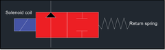
Some solenoid valves, such as 2/2 valves, do not invoke a spool, but rather a plunger. When the coil is electralised, the plunger moves upwards to allow for the media (i.e. fluid or compressed air) to pass. 2/2 valves do not allow the media to change fluid path direction. It is constrained to opening or closing a port.
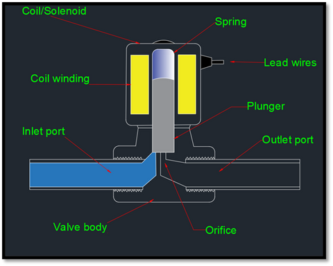
Diagram 1. 2/2 Valve (On/Off Valve)
Taxonomy of Pneumatic Symbols for Solenoid Valves:
Pneumatic solenoid valves are often specified by two numerical digits, the first determining the number of ports and second determining the number of positions. Hence, a 3/2-way valve has three ports (two inlets one outlet or one inlet two outlets) and two positions (e.g. open or closed).
How solenoid valves are specified: [# of ports]/ [#of positions]
Some of the common symbols related to pneumatic solenoid valves are given below. These symbols are often printed on the body of the solenoid valve. If you are looking for a replacement, you can identify the type of valve from the symbols.
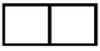 |
Two squares indicate the valve has two positions; e.g., on or off. |
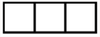 |
Three squares indicate that the valve has three positions; e.g. on, off, and an intermediate state. |
 |
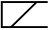
Arrowed lines represent the directions of flow from ports, which are usually numbered or lettered. |
 |
This is the symbol which indicates closed port. |
 |
The symbol indicates a position that has a closed state. |
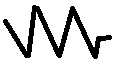 |
The symbol for spring, which often is on the side of the rest position of the valve. This is because an internal spring will mechanically return the spool/plunger to its default position and corresponding flow path. |
 |
This is the symbol for a solenoid coil |
 |
This is the symbol for the 2/2 valve. It represents two ports (inlet and outlet) as well as two states (either open or closed). |
 |
This is the symbol for a 3/2 valve having 3 ports and two positions. Commonly used for mixing purposes. |
 |
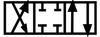
This symbol indicates a 4/2 valve having 4 ports 2 positions. |
 |
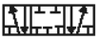
This symbol indicates a 4/3-way valve having 4 ports and 3 positions. |
 |
This symbol indicates a 5/2-way valve containing 5 ports and 2 positions. These are most often used with single acting cylinders – one position for extension, and the other position for suspension (i.e. no compressed air entering the cylinder). The return stroke of a single acting cylinder is usually mechanized by a spring in the cylinder. |
 |
This symbol indicates a 5/3-way valve which contains 5 ports 3 positions. These are most often used with double acting cylinders. One position for extension, one for closed, and the other for retraction. |
3. Choosing the right Number of Ports:
Choosing the number of ports depends upon the application at hand. For example, for applications which are to permit flow in a binary manner (i.e. either on or off), such as filling a tank, a 2/2 valve would be appropriate. For an operation that requires mixing or separation of fluids, a 3/2 valve would be most appropriate, as there is an additional exhaust port. If a 2/2 valve were chosen for mixing or spray-painting purposes, the residual air pressure may result in unsatisfactory results.
4. Choosing the right Number of Ways:
The second numeral after the forward slash (e.g. 5/2) determines the number of positions that a solenoid valve has. Any solenoid valve must have two states or more, lest it be no longer a valve but rather a junction of compressed air flow. (Note that a valve can also have an infinite number of positions, such as flow regulators which mechanically and incrementally adjust flow rate. Infinite position valves are, however, usually not controlled by solenoids.)
Common Valve Types:
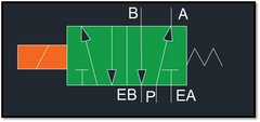
3/2 Valve
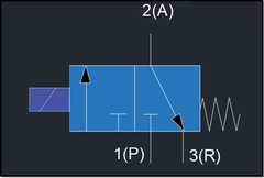
A 3-way solenoid valve has three states; opened, closed and a middle position. As shown in the figure, the 3/2-way valve has two positions. When the valve is ‘open’, air flows from the inlet A1 to the outlet B1. When the valve is closed, compressed air flows from the outlet port (labeled 2) to the exhaust port (labeled 3).
2/2 Valve
A 2-way valve is used for applications that are binary in nature, such as filling up a tank. As shown in the figure, the solenoid valve has two ports and two conditions. When the coil is energized, the fluid is permitted to move from the inlet port to outlet port.
5/2 Valve
A 5/2-way solenoid valve has the following characteristics:
- Two Outlet Ports (to actuators)
- One Inlet Port (from compressor)
- Two exhaust Ports
- Two Positions
In the first state, fluid is permitted to flow to one of the outlet ports, and any remaining compressed air in the actuator, tubing or valve is permitted to exhaust through one of the exhaust ports.
In the second state, fluid is permitted to flow to the other outlet port (and hence, fluid is no longer flowing to the first outlet port. Similarly, any excess air in the system is allowed to vent through the other exhaust port.
5/3 Valve
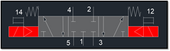
5/3 pneumatic solenoid valve has three positions, as well as two solenoid coils (in contrast to the one possessed by a 5/2 valve). When either of the coils is electralised, the fluid flows from a pressure port to an outlet port. If neither of the coil is energized, the valve returns to a center default position which can be result in one of these two scenarios, which depends on whether the valve is normally closed or normally open (see section 6):
- Both ports remain open
- Both ports are closed
If the valve is normally closed, then the centre position allows for the actuator to be stopped mid-stroke. On the hand other, if a valve is normally open, then the centre position allows for compressed air to exit from the pneumatic system, including within the actuators, to the exhaust ports of the valve. It is important to note that compressed air is not necessarily vented but is permitted to vent. In theory, the actuator should also stop mid-stroke – but the confluence of other forces may displace it. For example, gravity may take over such that the actuator falls to its most extended or most retracted position, as there is n
5/3 solenoid valves are most often used in double acting actuators, where the return stroke is accomplished by electralisation of the second solenoid, rather than an internal spring within the actuator.
5. The Voltage of Solenoid valve:
Solenoid valves are designed to work with a solenoid coil, which consists of copper wound in such a way as to generate a magnetic field when electricised. Coils and valves are usually modular, meaning that coils with different voltages can be installed on the same solenoid valve.
The most common voltages for pneumatic solenoid valves are 12 VDC, 24 VDC, 110 VAC, and 220 VAC. It is generally acceptable to supply a current at ±15% of these voltages.
The solenoid valve voltage should depend on the power supply at hand.
However, notice that applying less than the nominal voltage – that is, to ‘undervolt’ – may result in a slower "on" response time or the solenoid coil not energizing at all. On the other hand, to apply an overvoltage will result in the spool moving more quickly, and hence, one may perceive a faster response time. However, extreme overvoltage could lead to significant damage to the solenoid valve (see trouble shooting article). We do not generally recommend one to decide voltages based on response times, as the effect is marginal for the small size of spools in pneumatics.
6. Other Specifications
6.1 Normally Open (NO)
5/3 Normally open valves allow for compressed air to pass through when the solenoid is no longer electralised.
Choosing a N.O. valve when a NC valve is required is likely to result in overheating of the solenoid coil, as it is electralised for longer periods of time.
6.2 Normally Closed (NC):
Conversely, in normally closed valves, the default position (when no coils are electralised) is one where all ports are blocked and compressed air is no longer permitted to pass through.
6.3 Direct vs. Pilot operated
Solenoid valves can also be either pilot operated or directly operated based. Within large pneumatic valves, the spools require additional force (in addition to magnetic forces) in order to be moved. Pilot-operated valves are thus a two-stage process. First, when the solenoid coil is electralised, a miniature spool moves, so as to let some compressed air the valve. Secondly, this compressed air then helps move the main spool into its intended position and thereby letting more compressed air into the main valve chamber and then onto its intended destinations. These valves are thus pilot operated – as there is a pilot stage whereby compressed air helps move the main spool.
Directly operated valves do not require a pilot stage, and the electralistion of the coil is sufficient to move the main spool. Pilot operated valves are common in both hydraulics and pneumatics.
7. Other Considerations
7.1 Contaminants:
The functions of solenoid valves can regress over time due to contaminants from the surrounding environment. This is particularly applicable in certain production facilities. Contaminants can lead to pressure fluctuations by way of physical inhibition of the spool within the valve body. Contaminants can also accelerate corrosion.
In order to address such problems, FRL (Filter, regulator, lubricators) are installed upstream in the assembly to filter out any unwanted impurities, maintain and regulate nominal pressure in the orifices well as lubricate the medium through which fluid is moving.
7.2 Corrosion:
Compressed air passes through the solenoid valves. If the water content of the compressed air is high, then corrosion in the form of oxidation can occur within the valve as well as other pneumatic components.
It is standard practice to employ air filters (either auto-drain or self-drain) to remove water content from the compressed air.
Another consideration is the material composition of the valve. Stainless steel valves offer some of the best protection against chemical corrosion or oxidation.