

Pneumatic Flow Control Components
Introduction
In pneumatics, the control of flow is used to achieve two primary objectives: (i) the control of flow rate and hence, speed, and (ii) to restrict flow path. Both the former and latter come in the form of fittings and valves. The first half of this article will deal with speed controllers, and the second half will deal with other forms of flow control.
Speed Controllers
The operational speed of a pneumatic actuator is dependent upon the flow rate of the compressed air and the actuator piston area. For any given actuator, the piston area will be fixed, so speed cannot be controlled by adjusting the piston area. However, speed can be controlled by adjustment of the fluid flow (or restricting fluid from) from the actuator.
In pneumatics, the control of flow rate is most often achieved by a needle valve speed controller. For example, our Pisco JSC elbow flow control fittings can modulate flow rate via an internal needle valve. These are usually added to the meter-out position. In rare cases, such as when one is concerned with a single-acting cylinder, then the speed control fitting may be added in the meter-in position. However, this will often result in jittery actuation.
Some pneumatic speed control fittings will also have a check valve, in addition to a needle valve, to restrict back flow these types of fittings.
The choice of speed controller will depend on:
- Material composition (Technopolymer, Nickel plated brass, or stainless steel)
- Connection Thread Type (Rc, G, NPT, BSPP, BSPT)
- Connection size (1/8”, 1/4", 3/8”, 1/2”, 4mm, 6mm, 8mm)
- Adjustment Type (Manual Adjustment vs Recessed-Screw Adjustment)
Get in touch with us, if you are not sure which to use. We are happy to advise.
Other Flow Control Components
There are other flow control components that do not adjust the flow rate, but adjust the flow path. There are circumstances in which this is required. For example, one may wish to shut off flow completely on a certain path. Or, one may simply restrict any back flow.
Plugs
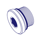
Figure 1. Pneumatic Male Plug
Plug fittings, quite obviously, restrict flow absolutely down a specific path. However, they cannot easily permit flow again without removal of the fitting and installation of another one.
Binary Ball Valves
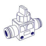
Binary ball valves, however, can permit or disallow flow conveniently. Unlike speed controllers, binary ball valves are for the most part binary: either flow is allowed completely, or it is not at all.
Pneumatic Check Valve
Pneumatic check valves, sometimes also known as one-way valves, allow for compressed air to flow in only one direction. They are installed in scenarios where backflow ought to be prevented. For example, it may be important to remove all risk of contamination due to backflow. Some equipment may be damaged by backflow. Check valves can also prevent siphoning and keep a vacuum seal.
The simplest construction of check valves is a ball and seat design. In this case, there will be a cracking pressure – or the minimum pressure required in order for compressed air to flow in the intended direction. The cracking pressure is determined by the force exerted by an internal spring. If the compressed air is flowing in the right direction, then the spring retracts, and air is permitted to flow. However, if air flows in the reverse direction, then the spring extends fully, and the ball covers the valve opening, thereby blocking flow.
British Pneumatics stocks and supplies brass and stainless-steel check valves (pneumatic and hydraulic) in a number of different sizes.