

Six Different Types of Pneumatic Actuators
Introduction
Minimally-speaking, pneumatics is a system of using compressed air to produce mechanical work in a manner intended by a system’s engineer. Mechanical work is usually in the form of moving, gripping, or other means of applying force to an object. The most common type of pneumatic actuator is the linear pneumatic cylinder. As the name implies, a linear pneumatic cylinder applies force in a ‘straight line’.
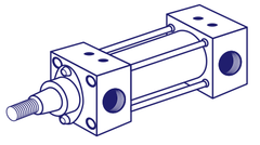
Figure 1. Tie Rod Pneumatic Cylinder
(Tie rods extending through the sides of the cylinder body grant the cylinder additional strength by increasing the yield threshold to guard against any shear forces).
There are a large range of pneumatic actuators, each designed for a separate function. In this article, we will investigate the different types of pneumatic actuators, their construction, and functions.
The Types of Pneumatic Actuators:
1. Linear Pneumatic Cylinder
This is the most common type of pneumatic cylinder on the market and in use in general industry. It is constructed out of a cylindrical tube (usually, in aluminium), a piston connected to a rod, and two caps. Compressed air exerts a force on one or both sides of the piston (depending on whether the cylinder is single-acting or double-acting), which results in the extension or retraction of the rod. The rod is coupled with a load such that mechanical work is performed.

Figure 2. Cylinder Construction
|
Box 1. How much force does a cylinder produce? The force applied during a stroke depends on the area of the piston and the system pressure. The force during outstroke is given by F = Pressure x πR2 (πR2 is the area of the piston) The force during an instroke is given by F = Pressure x (πR2 – A), where A is the area of the rod. (The area of the rod can be given by πr2.) |
2. Compact Pneumatic Cylinder
A compact pneumatic cylinder operates on the same principles of a general linear pneumatic cylinder. That is – compressed air exerts force on one or two sides of an internal piston. However, it is designed to be in a much smaller size. As a result, its stroke length will also be smaller. For this reason, compact cylinders are sometimes called short stroke cylinders. Although, they are smaller, te force generated is dependent upon bore size and line pressure.
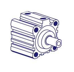
Pancake cylinders are also appropriate where space is limited. They have round bodies and are flat in profile. Although other innovations may exist, in principle, they are the same as compact pneumatic cylinders and general pneumatic cylinders.
4. Round-body Cylinder
Round-body pneumatic cylinders, as its name suggests, has a round body. Their form factor allows for a variety of different rod and end cap construction in order to aid with mounting. For example, round body cylinders may have a built in clevis such as for it to be mounted on a fixed pivot.
Can be mounted in a variety of ways. See our mounting article.

5. Rodless cylinders
The interior of a rodless cylinder is similar to any of the other cylinders in that there is a piston, whereby compressed air applies force on, at least, one of its sides. However, the piston is magnetic, and there is a magnetic follower mounted on the outside of the cylinder. As the piston moves inside the cylinder body, the magnetic follower moves with it. The load is coupled to this magnetic follower. However, the largest disadvantage is the force that the magnetic follower can provide.
This is because the force that can provided by rodless cylidners is determined by the breakway force between the piston and the follower. In some cases, where there is a more complex design, there can be a physical coupling between the piston and the follower. But this also has large disadvantage in that there is a tendency for leaks. That is – even if there are seals around the physical connection between the follower and piston, since the connection is consistently moving, seals will weaken over time.

6. Rotary Actuators
The last type of pneumatic actuator we will investigate are rotary actuators. Rotary actuators are very similar to electric motors, in principle, but are more compact. The output power (HP or kW) of an actuator is dependent on torque and rotation speed. The torque produced by a rotary actuator is directly related to the fluid pressure. When pressure increases, so does the maximum available torque.
There are two primary construction types for pneumatic rotary actuators: (i) rack and pinion, and (ii) vane type.
In the rack and pinion type pneumatic rotary actuator, a piston is attached to a rack gear such that when there is compressed air acting on the piston, the rack moves in a linear fashion and thereby, rotating a gear. The rotating gear is then converted by some oscillating rotary motion in some manner.
In a vane type pneumatic rotary actuator, compressed air acts on one side of a vane and thereby, rotating the vane. However, there may be considerable side- loading on the shaft of a single vane type design. Most vane rotary actuators will have a double vane design.
